How to connect lithium ion batteries
- 03/06/2024
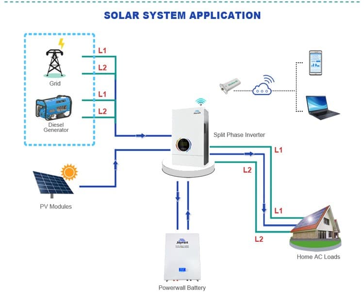
(solar system diagram)
When connecting LiFePO4 batteries to an inverter for an off-grid solar system, it’s essential to grasp the key components of these lithium-ion batteries. Let’s explore them:
- 1. Battery Components:
- Battery Cells: The fundamental building blocks that store energy. High-quality cells are crucial for overall battery performance.
- Battery Management System (BMS): Provides comprehensive management and protection for the battery.
- DC Circuit Breaker: Safeguards against overcurrent and short circuits.
- Thick Copper Panel: Ensures efficient current flow within the battery system.
- Housing (Plastic or Metal): Protects the battery components and provides structural support.
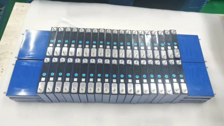
(battery cells)
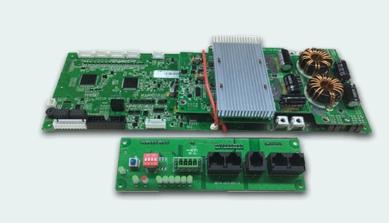
(BMS)
2. BMS Specifications and Functions:
- Voltage Warning and Protection:
- Monitors voltage at the module and individual cell levels.
- Triggers warnings and protective measures to prevent overcharging or over-discharging.
- Current Warning and Protection:
- Customizable maximum operating current.
- Alerts and safeguards against excessive current flow.
- Temperature Monitoring and Protection:
- Four sensors for the battery pack and one for the BMS.
- Ensures safe operation within temperature limits.
- SOC and SOH Calculation:
- Accurately calculates State of Charge (SOC) and State of Health (SOH).
- Displays precise battery status.
- Communication with Inverter or PC Monitor:
- Reports battery data for real-time monitoring.
- Enables seamless integration with the energy system.
- Pre-Charge and Pre-Discharge Logic:
- Ensures safe use during charging and discharging.
- Operating Modes:
- Switch-Off Mode: Temporarily disables battery operation.
- Sleep Mode: Reduces power consumption during idle periods.
- Operating Mode: Normal battery operation.
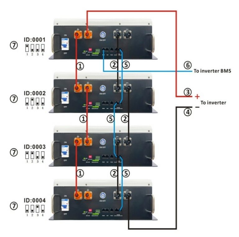
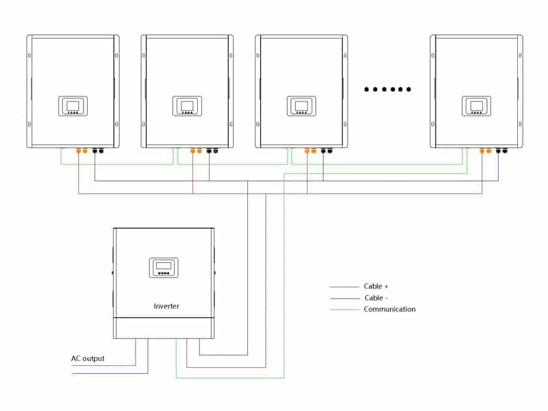
(battery parallel connection)
Here are the steps to ensure the batteries work properly and safely:
- 1. First, decide how many batteries you need to parallel to meet your power and capacity requirements.
- Please note: The BMS current should be greater than the inverter start current, or it will damage the battery or the battery can not start to work due to current protection. This is because the inverter has large capacitors that need to be charged when it is turned on, and this causes a high surge current that can exceed the BMS current limit. To avoid this problem, you can use a pre-charge circuit or a current surge limiter to reduce the inrush current and protect the battery and the BMS. You can also program the inverter and the charging source to not exceed the safe voltage and current limits of the battery bank. Please refer to the user manuals of your battery and inverter for more details and safety precautions.
- 2. Next, connect the positive terminals of the batteries with each other using a suitable cable. Do the same for the negative terminals. This will create a parallel connection that will increase the total capacity of the battery bank while keeping the voltage constant.
- 3. Then, connect the positive and negative terminals of the battery bank with the corresponding terminals of the inverter using another cable. Make sure the cable size and length are appropriate for the current and voltage of the system.
- 4. After that, connect the communication cable of each battery with the parallel port of another battery. This will allow the batteries to communicate with each other and balance their charge and discharge.
- 5. Next, connect the RS485 port or CAN port of one of the batteries (the main battery) with the BMS port of the inverter using another communication cable. This will allow the inverter to monitor and control the battery bank.
- 6. Finally, set the dip switch on each battery according to its position in the parallel connection. The main battery should have its dip switch set to 1, and the other batteries should have their dip switches set to 0. This will assign different addresses to each battery and enable communication between them. (before set it, check if the BMS firmware has the inverter’s protocol, then it can communicate with the inverter).
Understanding Lithium-Ion Battery Communication and Charging/Discharging Curves
1. Importance of Battery Communication
When integrating a solar system with a lithium-ion battery, establishing communication between the battery and the inverter (or solar controllers) is crucial. Here’s why:
State of Charge (SOC) and Capacity: Without communication, the inverter relies solely on voltage to determine charging points. However, for lithium-ion batteries, voltage changes do not accurately reflect their real power or SOC. By enabling communication protocols, the inverter can directly read and monitor battery data, allowing precise control of charging based on the actual SOC.
Optimized Charging: Communication ensures that the inverter adjusts charging parameters according to real-time battery conditions. This optimization leads to better performance, longer battery life, and improved overall system efficiency.
2. Charging and Discharging Curves
Charging Curve: CC-CV Method
Constant Current (CC) Phase: During the initial charging stage, the battery experiences constant current while its voltage rises. When the battery reaches its full charge cut-off voltage, the constant voltage (CV) mode takes over.
Constant Voltage (CV) Phase: In this phase, the charging current decreases gradually until it reaches below 0.05C. The battery reaches its full charge voltage after the CV mode starts (as soon as one of the cells reaches its full charge voltage). However, this doesn’t mean the battery is 100% charged.
Trickle Charge Mode: After reaching full charge voltage, trickle charge mode kicks in. The remaining battery capacity is charged while balancing the cells. Only when every cell has reached its full charge voltage is the battery pack truly 100% charged.
Discharging Curve
- A flat discharge curve is desirable because it indicates constant voltage throughout the battery discharge. However, a flat curve may prevent the battery from delivering close to 100% depth of discharge (DoD) due to cell cutoff voltages.
- Lithium iron phosphate (LFP) cells exhibit flatter discharge curves compared to nickel manganese cobalt (NMC) cells. LFP cells deliver lesser DoD but have fewer balancing issues when assembled into battery packs.
(25.6V100Ah LiFePO4 battery)
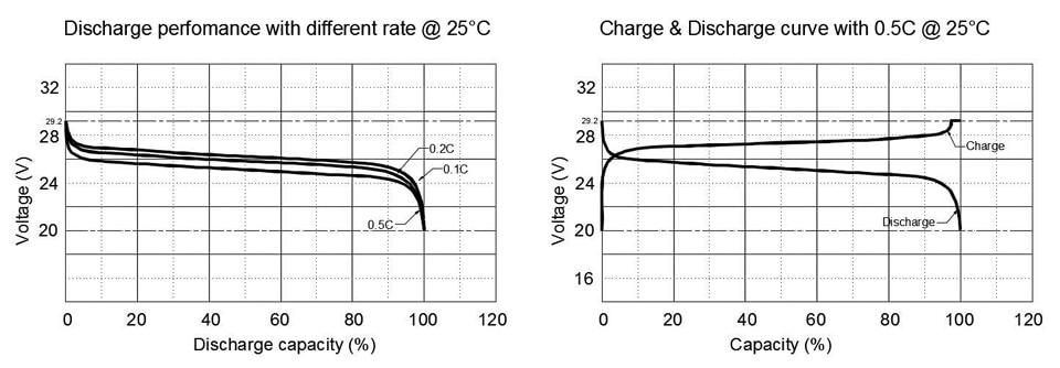

(25.6V100Ah LiFePO4 battery)
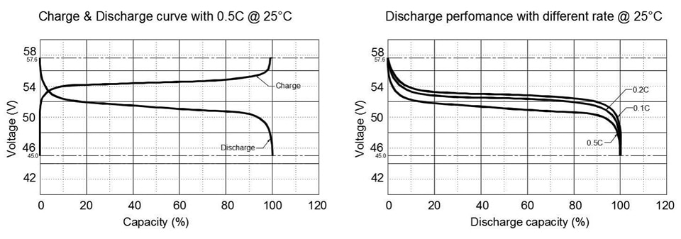

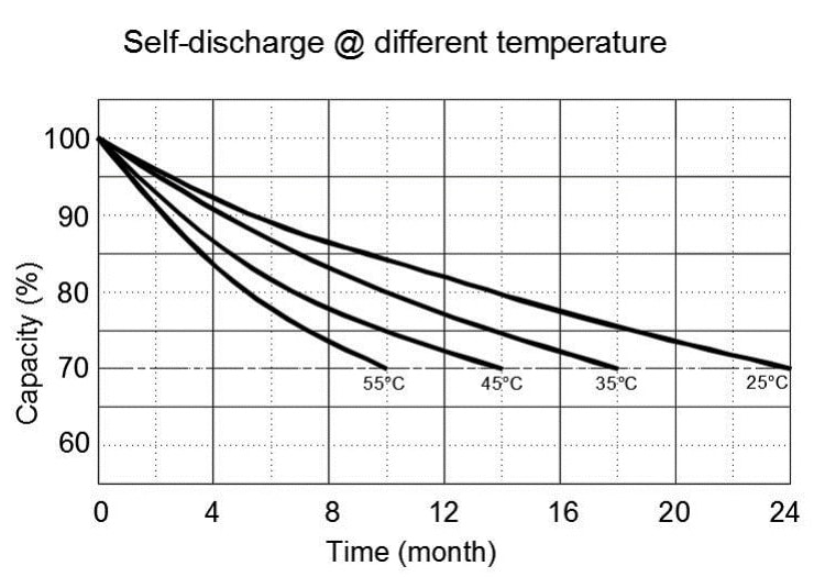
(51.2V100AH LiFePO4 battery performance curve)
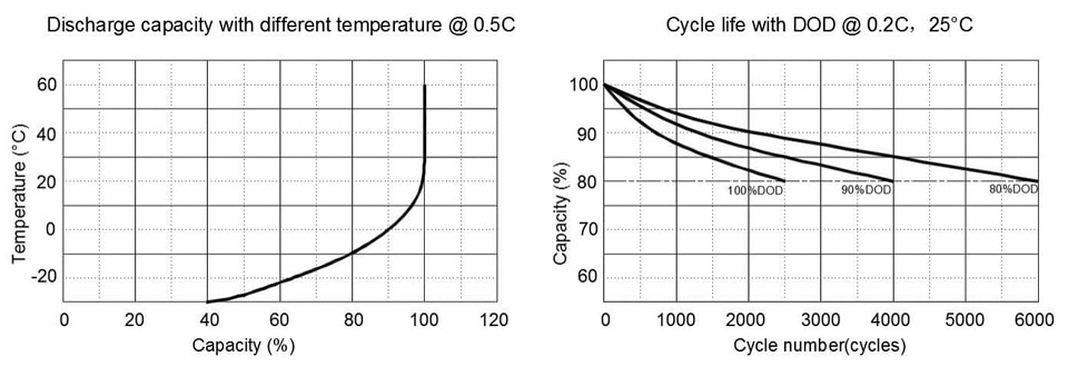
3. Battery Lifecycle Considerations
To extend battery lifespan, consider setting the over-discharge threshold at 80%. This practice significantly increases the cycle life, especially for higher-capacity batteries.
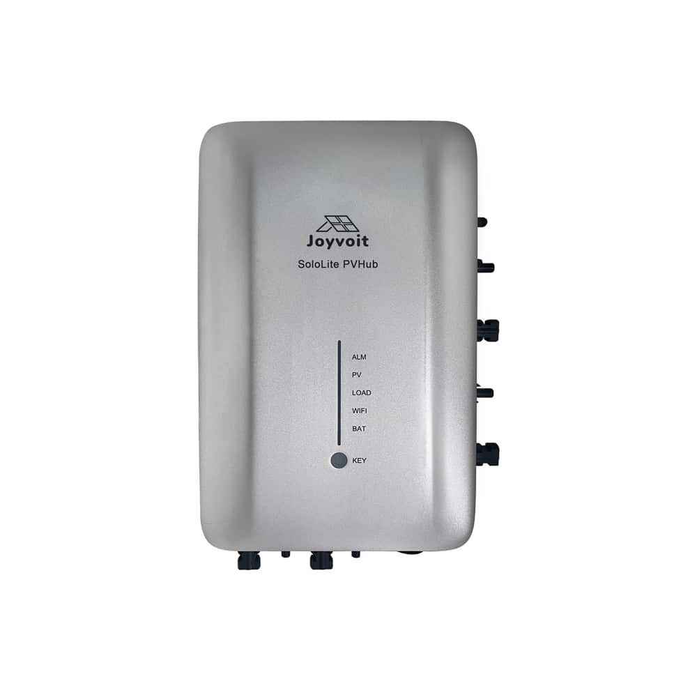
SoloLite PVHub
Model: SP20A1600H
1.Capture Solar Energy
2.Intelligent Distribution
3.Simple Monitoring
4.Customization at Your Fingertips
5.Automatic Updates
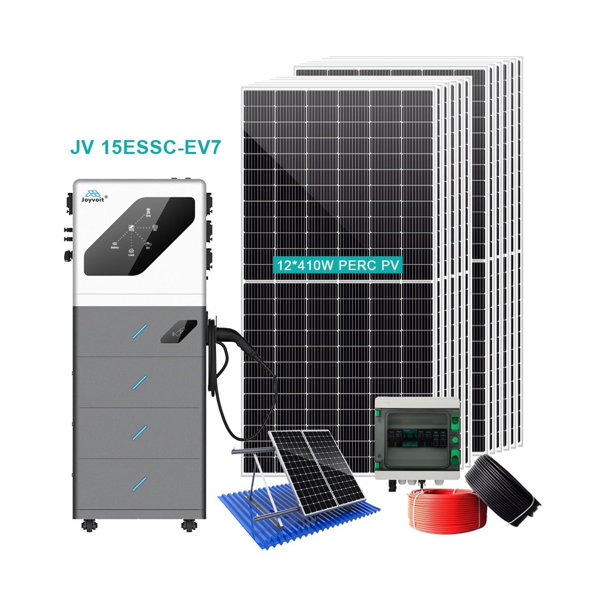
Hybrid Solar EV Charger 10-15KWh
Model: JV 10ESSC-EV7, JV 15ESSC-EV7
1.All-in-One Solution
Solar, battery storage, EV charging, power distribution
2.Easy setup, quick results
3.APP with real-time monoitor
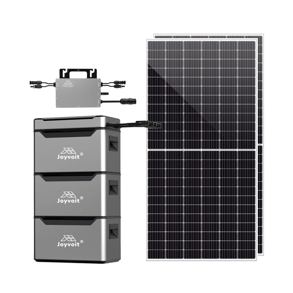
MESS Micro Energy Storage System
Model: MESS1000H
1.Versatile Solar Panel Compatibility
2.Easily Upgradable Stackable Battery
3.Seamless Integration with PVHUB
4.Adaptive Charging Modes for Optimal Efficiency
5.Monitor and Manage with Ease
Join the Solar Revolution with SHENZHEN SUNS ENERGY!
Join 80,000+ customers. Explore innovative solar solutions for a greener future. Act now for a brighter tomorrow!